Shipping options
Calculated individually for your region
Warranty
5 years from sale date
Opportunity to get samples and promotional materials
Manufacturer official website
You are on the official website of terneo and ZUBR brands manufacturer! Order directly from the manufacturer!
- Product info
- Characteristics
- Testimonials
A detailed description of ZUBR CV2 red operating principles and customization capabilities are described in detail below.
The description includes features of the latest firmware version, which may differ from yours.
Advantages of three devices in a compact 2-module-wide case
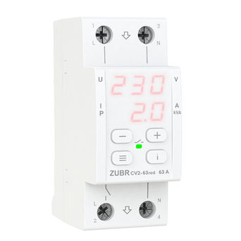
ZUBR CV2 red combines the advantages of three devices: compactness and maximum functions from ZUBR D2, current and power control from ZUBR MF, in-depth current limit settings from ZUBR I. At the same time, the cost of ZUBR CV2 red is more attractive than ZUBR MF.
ZUBR CV2 red protects the equipment from high and low voltage, from zero break, and also limits current or power consumption. When the current or power is exceeded, the load is disconnected after a specified delay time.
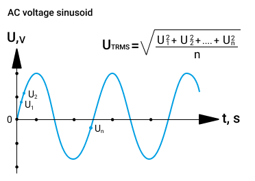
High accuracy of voltage measurements with TrueRMS
TrueRMS reduces the effect of network interference on the accuracy of voltage measurement when the voltage shape is different from the sinusoid. Thanks to this algorithm, the relay will turn off the load before the voltage surge negatively affects the connected devices.
Professional load switch-off model
You can activate a professional switch-off time delay model to reduce the number of outages of modern equipment that works stably under certain power voltage deviations. Thus, the use of ProModel allows you not to turn off the equipment in case of voltage deviations that are safe in size and duration.
The creation of ProModel mode is based on the ITIC (CBEMA) Curve:

Default load shedding rate and if Professional shedding model is applied
Overheating protection
The temperature sensor inside the case provides safety and disconnects the load if the temperature inside the case exceeds 80 ° C, while the “oht” message flashes on the screen. After the temperature drops below 60°C, the device will turn on the load and restore operation.
If the protection works more than 5 times during the day, the relay will be blocked to pay the user's attention to the current non-standard situation until the temperature inside the case becomes below 60 ° C («oht» will stop flashing) and one of the buttons is pressed. If you want to find out the temperature of the thermal protection sensor: to do this, during overheating, press the «i» button, and if there is no longer overheating, hold down the «i» button for 21 seconds.
Accident load switch-on delay
By default, there is a minimum delay in the relay from the plant to turn on the load of 3 seconds. Depending on the type of your connected equipment, you can set it in the range from 3 to 999 seconds. For equipment sensitive to frequent voltage outages, for example, refrigerators and air conditioners, it is recommended to set the switch-on delay to 2-3 minutes.
According to default settings, the delay is counted from the moment the voltage is stabilized, in the settings it is possible to select another type of delay when the countdown begins from the moment the relay is turned off.
To quickly restore voltage throughout the house after an emergency, install ZUBR R116y for refrigeration equipment that is demanding for the duration of switch-on delay. And for D2, make such a delay minimal.
Alarm log for 100 values
The log is capable of storing in non-volatile memory 100 recent emergency actuations (for example, voltage when the relay is turned off or overheating protection is triggered).
Operation comfort
ZUBR D2 has a very convenient standardized I/O connection, there is no need to use a neutral terminal when connecting. The device is set up with only three buttons. The forth button «i» is used to view the alarm log and decrypt the abbreviations of menu items. The digital screen constantly displays the voltage value, as well as system information. You can adjust the brightness of the screen and the indication in standby mode.
Easy installation
ZUBR D2 voltage relay is very compact, it takes space of 2 standard modules in the switchboard. It is installed in the switchboard on a standard 36 mm wide DIN rail. If there is increased humidity in the room or there is a possibility of water entering the device, then the board must meet the IP55 protection class (according to 14254 GOST).
Additional options for better settings
1. Switch-off time in case of voltage failure
It is necessary for those whose network is overloaded with powerful equipment or its quality is insufficient and this leads to frequent voltage drops and, as a result, frequent relay actuations. In such a situation, it is impossible to directly influence the circumstances, but it is possible to reduce the number of relay disconnections by taking the time that the relay will wait before disconnecting the load.
In order to properly adjust the switch-off time, the data on the protected equipment must be guided.
The time adjusted in this way will only be valid when the voltage is reduced from 154 to 176 V (when the professional model is turned on) or from 120 to 210 V (when the professional model is turned off). In other situations, the switch-off time is fixed (see table above).
2. Adjustable hysteresis by voltage
In the case when the relay is often triggered, but there is no longer any way to expand the response limits, and the current voltage in the network is close to the exposed limit and it does not stably make sense to use hysteresis as an additional tool to reduce the number of actuations. The addition of hysteresis makes it possible to optimize the number of trips, making sure that the voltage has become more stable and less than the established limit. Optimal voltage limits and hysteresis settings allow you to weed out unstable voltage close to the established limits.
Operation logic of the relay with the established hysteresis: after actuation by the limit of the voltage relay, it will turn on the load when the voltage normalizes to the established limit and even additionally by the hysteresis value.
3. Protection from frequent operations in case of unstable network
Limits the number of repeated relay operations in a row to eliminate their detrimental effect on protected equipment. Without such protection, equipment sensitive to frequent operations, such as a refrigerator or air conditioner, can fail. When the maximum number of actuations is reached in a row, the protection will work, the relay will be blocked and the load will turn off until the user pays attention and presses one of the relay buttons.
Frequent relay actuations can be caused by:
— Elimination of neutral in the network.
— Network voltage is close to set limits and is not stable. In this case, the relay response rate can optimize the following settings:
а) increase the values of the relay operation limits in accordance with the quality of the network so that the protected equipment is tolerant of them;
б) adjust the voltage hysteresis value.
Technical properties of ZUBR CV2 red
- Product category:
- voltage relay
- Current, A:
- 63
- Installation method:
- on the DIN rail
- Number of phases:
- 1 ph. 230 V
- Thermal protection:
- yes
- TrueRMS:
- yes
- Prof. switch-off delay:
- yes
- Lower voltage limit:
- 100-210 V
- Upper voltage limit:
- 230-280 V
- Rated load capacity:
- 14 400 VA
- Load switch-off time at voltage reduction:
- 0,1-10,0 sec (≥100 V), not more than 0,03 sec (<100 V)
- Time of load switch-off when voltage is exceeded:
- not more than 0,03 sec
- Main current limit:
- 0,5–63 А
- Active power limitation:
- 0,1–14,4 kVA
- Rated load power:
- 63 А (max 80 А for 10 minutes)
- Load switch-on delay time:
- 3–999 seс
- Load switch-off delay time:
- 0–240 seс
- Тип реле:
- polarized
- Supply voltage:
- 100–420 V
- Wire section:
- not more than 16 mm²
- Weight:
- 0,19 kg ± 10%
- Overall dimensions (W x H x D):
- 36 х 85 х 66 mm
- Number of actuations under load, not less than:
- 10 000 cycles
- Number of actuations without load, not less than:
- 500 000 cycles
- IP rating according to GOST:
- ІР20
- Capacity, VA:
- more 10 000
- Supply package:
- relay, warranty certificate, technical passport, instruction, the packing box


