Electrical switchboard assembly - rules, diagram and installation
Electrical switchboard assembly steps
The assembly and board connection works can be divided into steps. Each of them has its own rules and features. By adhering to them, you can assemble an electric board that provides a high degree of energy protection.
Step 1. Evaluation and formation of consumer groups.
At this step, it is necessary to allocate consumers with the highest power (2 kW or more). They include electric ovens, stoves, water heaters, washing machines, and a heating floor.
It is recommended to connect such consumers to a separate group.
It is also recommended to create separate groups for lighting, sockets.
To select equipment, you need to summarize data on the capacities of each consumer (indicated in the passports), as well as add about 30% of the safety margin. According to the results of calculations, components are selected: switching devices, circuit breakers, GFCI, etc.
Stage 2. Scheming.
The finished scheme of the electrical board allows you to clearly imagine the future location of the elements in the switchboard. This will facilitate the assembly process as well as possible repairs or upgrades. In the diagram, you must select user groups, and also indicate the order of connection of components.
Step 3. Selection of the electrical board and place of installation.
At this step, the calculation is carried out, as well as the selection of equipment, the selection of the location, as well as the purchase of the switch box. This stage of preparation is the most important, because mistakes made can affect the final result. The switch box should be selected in the following sequence:
3.1. Selection of components by consumer groups and calculation of the number of modules.
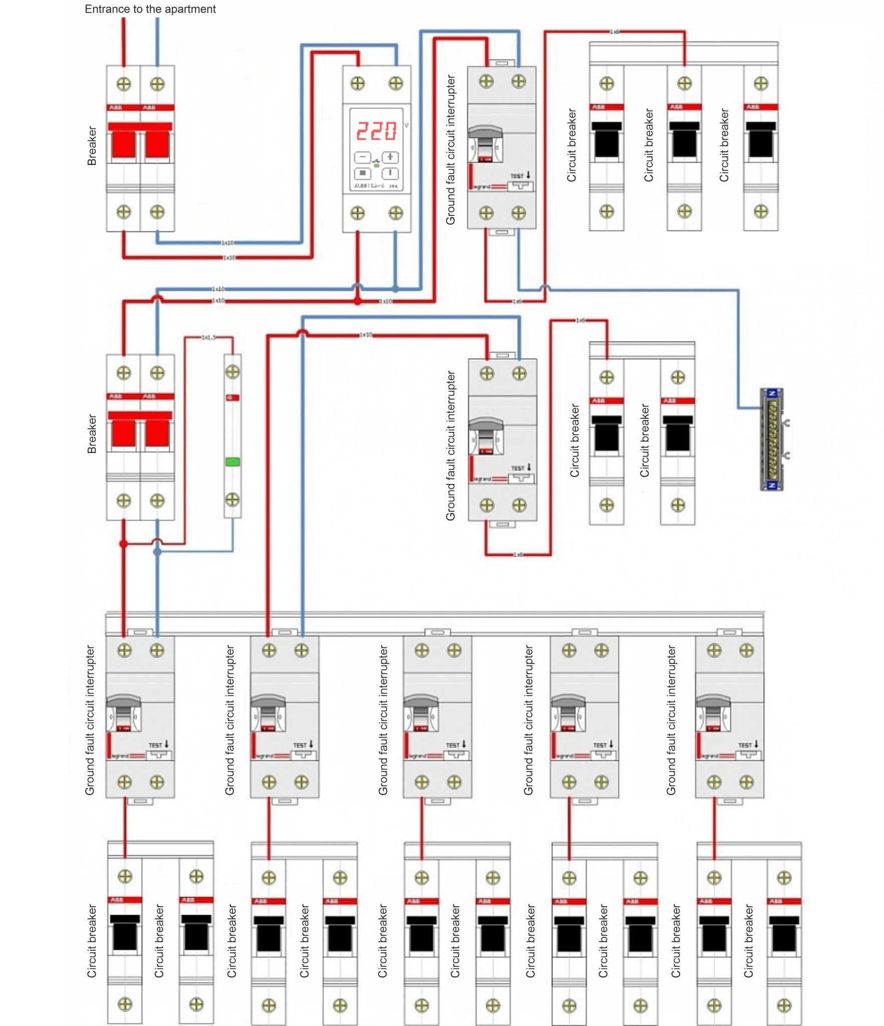
According to the drawn scheme, it is necessary to determine exactly what equipment will be needed and of what capacity. Here are the main elements that are installed in the electric board:
- The starting switch is used to supply power to the board, and also allows you to quickly turn off the power supply.
- Counter - measures the consumed electricity.
- Voltage relay - protects the technician from excessive voltage surges.
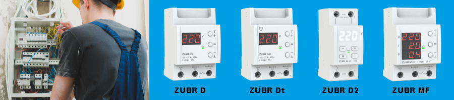
- Measuring devices (voltmeter, ammeter) - these devices are connected if it is necessary to visually monitor voltage and current. When installing the ZUBR voltage relay or the ZUBR multifunctional relay, no additional measuring devices are required.
Circuit breakers are installed for protection against closing as well as overloads. For example, consumers with a power of 2 kW or more are connected through a circuit breaker of 25A or 32A. To connect socket lines and lighting lines, automatic machines of 10A or 16A are enough. - GFCI or differential breaker is a necessary element for protection against leakage (electric shock). It is advisable to put the GFCI on each dedicated line.
- Also, special strips, terminals, buses, cables, etc., will be required for connection.
- After the list of components is determined, you need to calculate how much space they will occupy and what size the board needs. The dimensions of the elements are standard and are determined by the number of modules - 1 module is 17.5 mm. There should also be some free space for future upgrades.
You need to pay attention to the quality of the elements that will be installed in the electric switchboard. Cheap low-quality products should not be purchased, since this depends not only on the stability of the electricity supply of the apartment or house, but also on energy security. DS Electronics is a manufacturer of high-quality ZUBR voltage relays and multifunctional relays. All ZUBR relays have a 5 years warranty.
3.2. Selection of installation location.
Often, builders provide a special niche for installing the switchboard, but if this is not the case, you will have to either do it by yourself or use hinged models.
When choosing a place, you need to take into account that there should be free access to it. Do not place it in wardrobes or any other furniture. Also, the board should be sufficiently remote from various heating devices, gas equipment or other flammable materials. The recommended distance from the floor to the board is 1.5-1,7 m, to the doorway - 15 cm minimum.
3.3. Choosing an electrical switchboard.
The size of the box should correspond to the calculated value by the number of modules, as well as the size of the niche. The switch box may be made of metal or non-flammable plastic. When purchasing, be sure to check the presence of a passport and certificate, which contain data on the manufacturer, materials, operating rules, etc.
Step 4. Direct assembly of the electrical switchboard.
Usually, the switch box is equipped with special removable guides, to which DIN-rails are attached for installing equipment.
It is convenient to do preassembly on the table.
For equipment installation, line or group connection schemes are most often used.
Line scheme means placing elements one after the other. It is simple to implement, but in the event of an accident it will be difficult to establish the source of the fault.
In case of group connection, modules are connected in groups to each consumer line. Such a scheme is more difficult to assemble, but allows you to immediately determine the problem zone by the machine that worked.
The board elements should be assembled in the following order:
- Installation and fixation of modules on DIN-rails according to a preliminary scheme.
- Connection of the elements to the starting switch by using a terminal strip.
- Connection of phase by cables with tips.
- Zero bus installation.
- Check of connection reliability by using a screwdriver.
- Connection of the input switch to the power supply and check of the correct actuation of the elements.
- Check of the voltage on the elements using a multimeter.
Step 5. Installation of electrical switchboard and its connection.
Installation of electrical board is realized after completion of all dusty repairs and finishing works. The box is fixed in the selected place, guides with DIN-rails and equipment are fixed inside using self-cuts.
Working (N) and protective (PE) zero buses are installed. Wires are brought in and fixed.
Before using the board, make sure that all elements of the electrical system are assembled and connected: switches, sockets, terminal boxes, etc.
Conclusion
The modern electric switchboard allows to ensure not only uninterrupted operation of the internal power grid. It is also able to protect equipment and people from possible accidents, as well as electricity leaks. That is why it is so important to carefully approach the selection of each element and not save on quality devices.